REV. 0
ADM1070
9
FUNCTIONAL DESCRIPTION
HOT CIRCUIT INSERTION
Inserting circuit boards into a live 48 V backplane can cause large
transient currents to be drawn as the board capacitance charges up.
These transient currents can cause glitches on the system power
supply and can permanently damage components on the board.
The ADM1070 is designed to control the manner in which a
boards supply voltage is applied so that harmful transient currents
do not occur and the board can be safely inserted or removed from
a live backplane. Undervoltage, overvoltage, and overcurrent pro-
tection are other features of the part. The ADM1070 ensures that
the input voltage is stable and within tolerance before being applied
to the dc-to-dc converter, which generates the low voltage levels
required to power the on-board logic. One such converter is the
Artesyn EXQ50. Go to www.artesyn.com for more information.
ARTESYN
EXQ50
C
LOAD
ADM1070
LIVE
BACKPLANE
0V
48V
R
SENSE
PLUG-IN BOARD
R1
R2
V
IN
+
V
IN
V
OUT
+
V
OUT
TRIM
FET
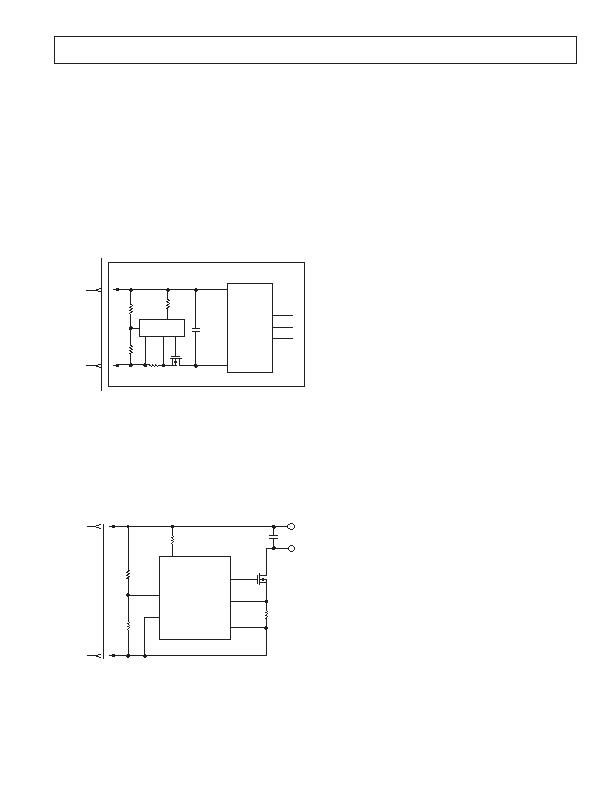
Figure 1. Topology
INITIAL STARTUP
The ADM1070 hot swap controller normally resides on a remov-
able circuit board and controls the manner in which power is
applied to the board upon connection. This is achieved using a
FET, Q1, in the power path. By controlling the gate voltage of
the FET, the surge of current to charge load capacitance can be
limited to a safe value when the board makes connection. Note
that the ADM1070 can also reside on the backplane itself, and
perform the same function from there.
TMER
ADM1070
R1
R2
UV/OV
GATE
SENSE
V
EE
Q1
R
SENSE
C
LOAD
V
OUT
R
DROP
16k
V
IN
0V
48V
LIVE
BACKPLANE
Figure 2. Circuit Board Connection
Figure 2 shows how a plug-in module containing the ADM1070
makes connection to the backplane supply. When the board is
inserted, the 48 V and 0 V lines connect. This powers up the
device with the voltage on V
IN
exceeding V
LKO
.
When the voltage at the UV/OV Pin exceeds undervoltage rising
threshold (V
UVR
) of 0.91 V, it is now inside the operating volt-
age window. It must stay inside this window for the duration of
the power-on reset delay time, t
POR
, which is dependent on the
value of C
T
.
When the device detects that the supply voltage is valid, it ramps
up the gate voltage until the FET turns on and the load current
increases. The ADM1070 monitors the level of the current flowing
through the FET by sensing the voltage across the external
sense resistor, R
SENSE
. When the sense voltage reaches 100 mV,
the GATE Pin is actively controlled, limiting the load current.
In this way, the maximum current permitted to flow through the
load is set by the choice of R
SENSE
.
If a change in the level of the supply voltage causes UV/OV to
fall below the undervoltage falling threshold of V
UVF
, or rise
above the overvoltage rising threshold of V
OVR
, then the gate
drive will be disabled.
BOARD REMOVAL
If the board is removed from a card cage, the voltage at the
UV/OV pin falls to zero (i.e., outside operating range) and the
gate drive is deasserted, turning off the FET.
CONTROLLING THE CURRENT
The ADM1070 features a current limiting function that protects
against short circuits or excessive supply currents. The flow of
current through the load is monitored by measuring the voltage
across the sense resistor, which is connected between the SENSE
and V
EE
Pins. There are three different types of protection offered:
1. If the voltage across the sense resistor exceeds the circuit
breaker limit voltage of 88 mV (rising) for the current limit
on time (t
LIMITON
), then a current fault has occurred and the
PWM cycle begins. The FET current is linearly controlled at
a maximum of 100 mV/R
SENSE
(via the gate drive) during
t
LIMITON
(see next section). The gate is then disabled for the
duration t
OFF
. This PWM ratio, which will always be 3%, is
given by t
ON
/t
OFF
.
A unique feature of the ADM1070 is the limited consecutive
retry function. An internal fault counter keeps track of the
number of successive PWM cycles that occur. The fault
counter is incremented after every fault is detected. If the
ADM1070 detects seven consecutive current faults, it is appar-
ent that the fault is not a temporary one and the device
latches itself off. The fault counter is cleared if a new t
ON
timeout does not occur within 2 t
OFF
of the previous
t
LIMITON
timeout.
发布紧急采购,3分钟左右您将得到回复。
相关PDF资料
ADM1073ARU-REEL
IC CTRLR HOTSWAP -48V 14TSSOP
ADM4210-2AUJZ-RL7
IC CTLR HOTSWAP LV TSOT23-6
ADVFC32SH
IC CONV V/F F/V MONO TO100-10
FAN4800ASNY
IC CTLR COMBO PFC/PWM 16-DIP
FAN4800AUN
IC PWM/PFC CTLR COMBO 16-MDIP
FAN4800CUN
IC PWM/PFC CTLR COMBO 16-MDIP
FAN4802MY
IC PFC CTRLR AVERAGE CURR 16SOP
FAN4802SNY
IC CTLR PFC/PWM COMBO 16-PDIP
相关代理商/技术参数
ADM1070EB
制造商:AD 制造商全称:Analog Devices 功能描述:ADM1070 Hot Swap Controller Evaluation Kit Documentation
ADM1072
制造商:AD 制造商全称:Analog Devices 功能描述:Dual, USB 2.0 Full/Standby Power Controller with Supply Steering
ADM1072ARQ
制造商:AD 制造商全称:Analog Devices 功能描述:Dual, USB 2.0 Full/Standby Power Controller with Supply Steering
ADM1073
制造商:AD 制造商全称:Analog Devices 功能描述:Full-Feature −48 V Hot Swap Controller
ADM1073ARU
功能描述:IC CTRLR HOTSWAP -48V 14TSSOP RoHS:否 类别:集成电路 (IC) >> PMIC - 热交换 系列:- 产品培训模块:Lead (SnPb) Finish for COTS
Obsolescence Mitigation Program 标准包装:119 系列:- 类型:热交换控制器 应用:通用型,PCI Express? 内部开关:无 电流限制:- 电源电压:3.3V,12V 工作温度:-40°C ~ 85°C 安装类型:表面贴装 封装/外壳:80-TQFP 供应商设备封装:80-TQFP(12x12) 包装:托盘 产品目录页面:1423 (CN2011-ZH PDF)
ADM1073ARU-REEL
功能描述:IC CTRLR HOTSWAP -48V 14TSSOP RoHS:否 类别:集成电路 (IC) >> PMIC - 热交换 系列:- 产品培训模块:Obsolescence Mitigation Program 标准包装:100 系列:- 类型:热插拔开关 应用:通用 内部开关:是 电流限制:可调 电源电压:9 V ~ 13.2 V 工作温度:-40°C ~ 150°C 安装类型:表面贴装 封装/外壳:10-WFDFN 裸露焊盘 供应商设备封装:10-TDFN-EP(3x3) 包装:管件
ADM1073ARU-REEL7
制造商:Analog Devices 功能描述:Hot Swap Controller 1-CH -80V 14-Pin TSSOP T/R 制造商:Analog Devices 功能描述:FULL FEATURED -48V HOT SWAP CTRL'R I.C. - Tape and Reel
ADM1073ARUZ
功能描述:IC HOTSWAP CTRLR -48V 14-TSSOP RoHS:是 类别:集成电路 (IC) >> PMIC - 热交换 系列:- 标准包装:50 系列:- 类型:热交换控制器 应用:-48V 远程电力系统,AdvancedTCA ? 系统,高可用性 内部开关:无 电流限制:可调 电源电压:11.5 V ~ 14.5 V 工作温度:-40°C ~ 85°C 安装类型:表面贴装 封装/外壳:10-TFSOP,10-MSOP(0.118",3.00mm 宽) 供应商设备封装:10-MSOP 包装:管件